Instrumented indentation · non-destructively on the component
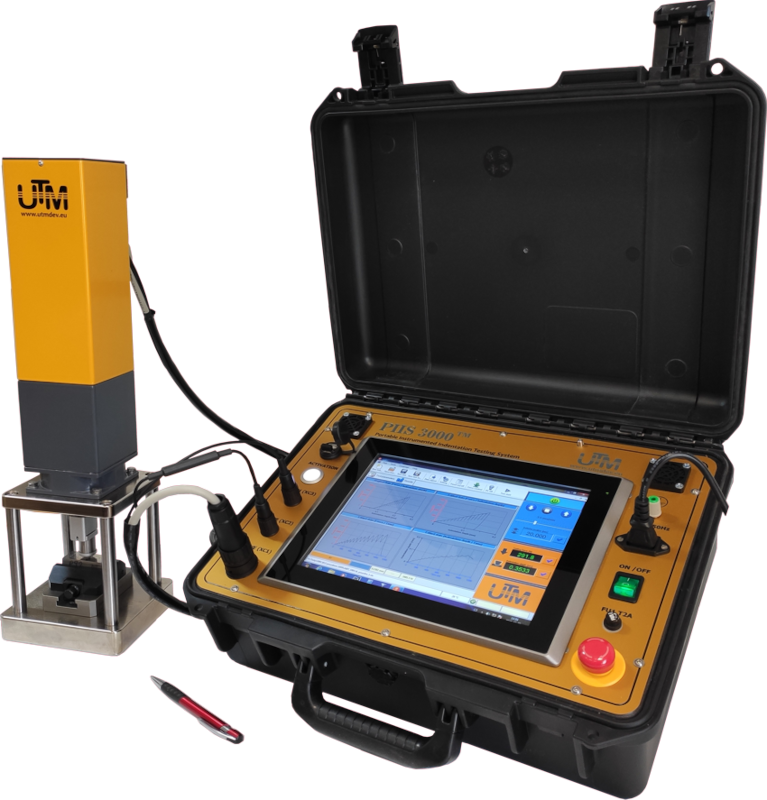
PIIS 3000
Mechanical properties and fracture toughness directly on a service-exposed component. Nothing is removed, no test piece is cut out.
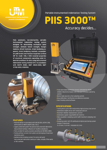
A fully automatic portable device for the non-destructive determination of structural component properties by instrumented indentation. The clamping system handles pipes, fillet and butt welds and flat surfaces.
3 kN
test force
0.01 µm
indentation depth resolution
±15 mm
indenter travel
10 kHz
data sampling
Technical parameters
The software computes properties for carbon, low-alloy, austenitic and high-strength steels.
- Test force
- up to 3 kN
- Indentation depth resolution
- 0.01 µm
- Maximum indenter travel
- ±15 mm
- Indentation rate
- 0.001–10 mm/min
- Data sampling
- up to 10 kHz
- XY positioning system
- X ±25 mm, Y ±5 mm, resolution 0.1 mm
- Standards
- ISO/TR 29381 · GB/T 39635-2020 · GB/T 37782-2019 · KSB0950
- Scatter band of mechanical properties
- usually less than 5–10 %
- Scatter band of fracture toughness
- less than 15–20 %
What the device determines
01
Yield strength and tensile strength
Directly on the component, with no material removal and no test piece cut out.
02
Young's modulus and Brinell hardness
From the same indentation, in a single measurement.
03
Fracture toughness
The critical stress intensity factor K IC in mode I (crack opening).
04
Strain hardening
The exponent, the constant and the accumulated plastic strain.
05
Residual stress in welds
The clamping system is built for pipes and for fillet and butt welds.
06
The report writes itself
The analytical report is generated automatically and the outputs are archived.
The test on site
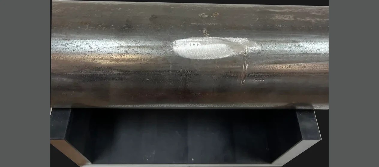
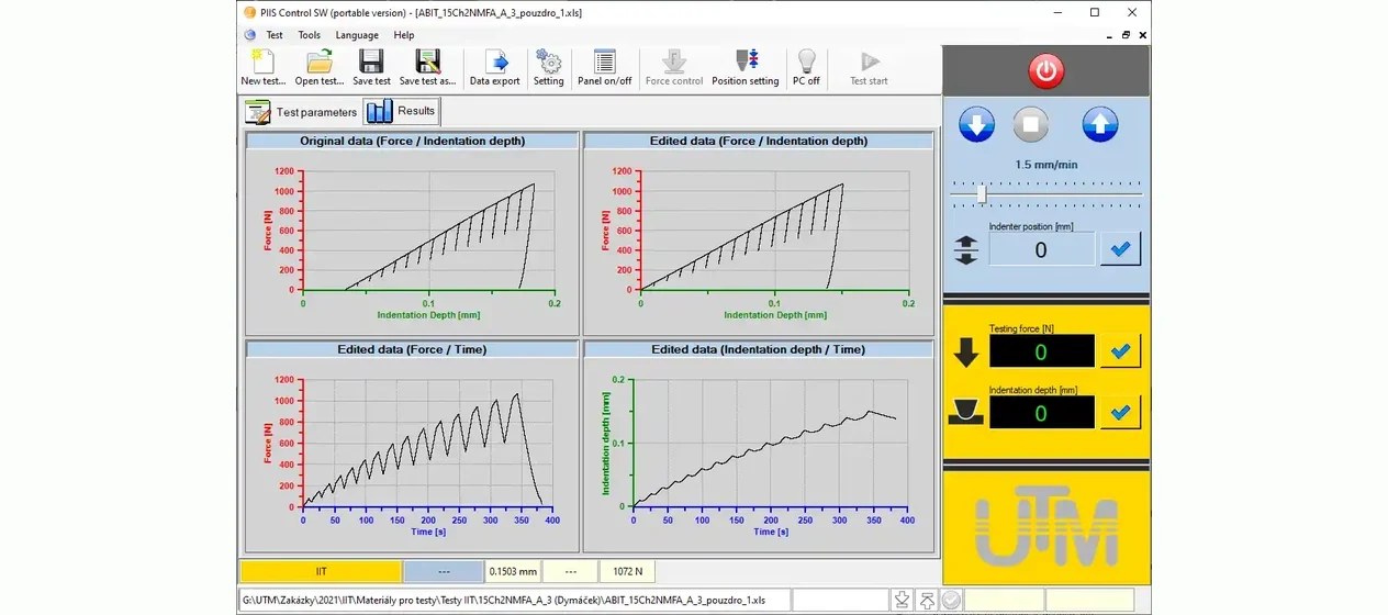
The measurement spot is first ground flat and marked on the component; the software then records the whole indentation and evaluates it straight away. Measurement is done on a cooled component — during an outage or on a dismantled part; afterwards the component goes back into service with no repair.
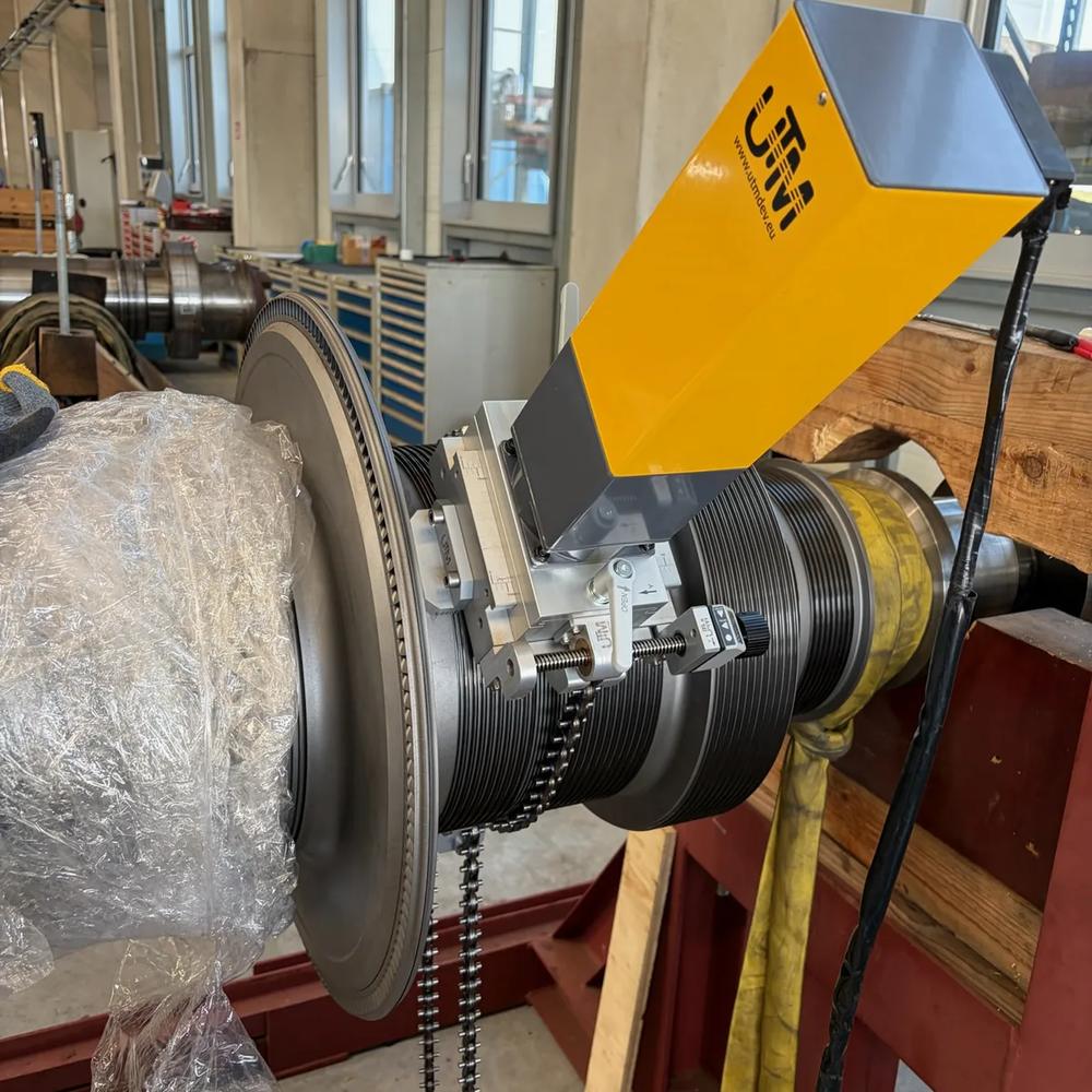
Measurement on a steam turbine rotor
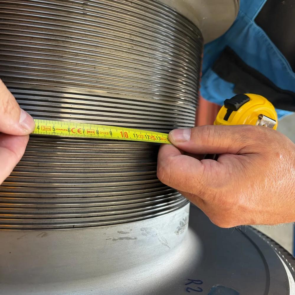
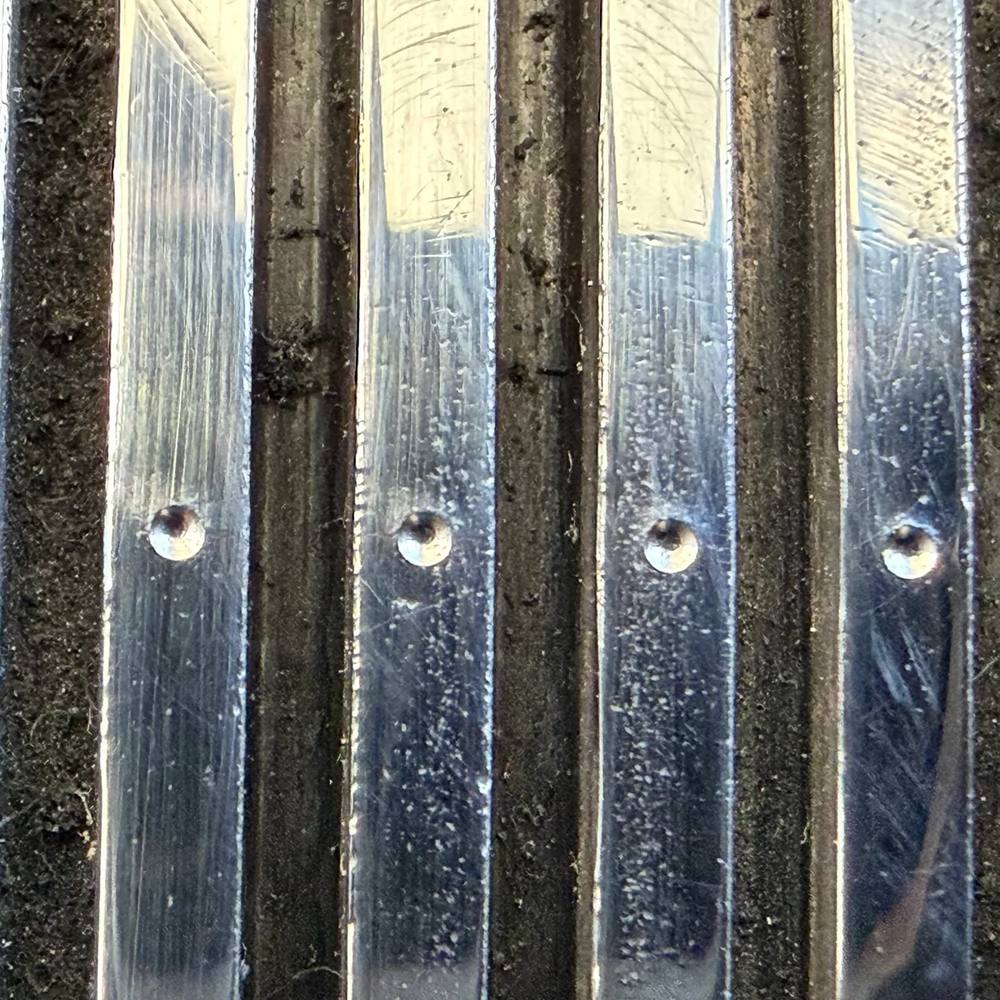
A rotor taken out for overhaul — cooled down and stripped. The assembly was chained directly onto the shaft and the indents were made in a row on ground flats between the grooves. Afterwards the rotor goes back into service exactly as it was — no block cut out, no welding, no repair.
Clamping options
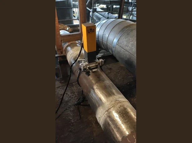
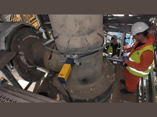
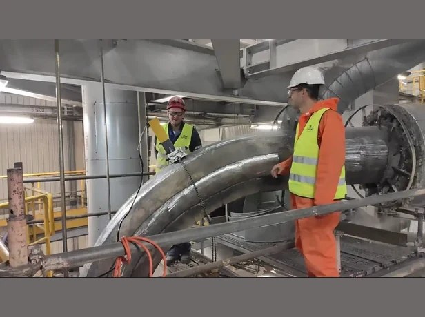
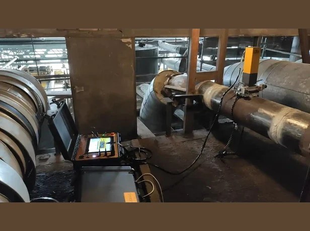
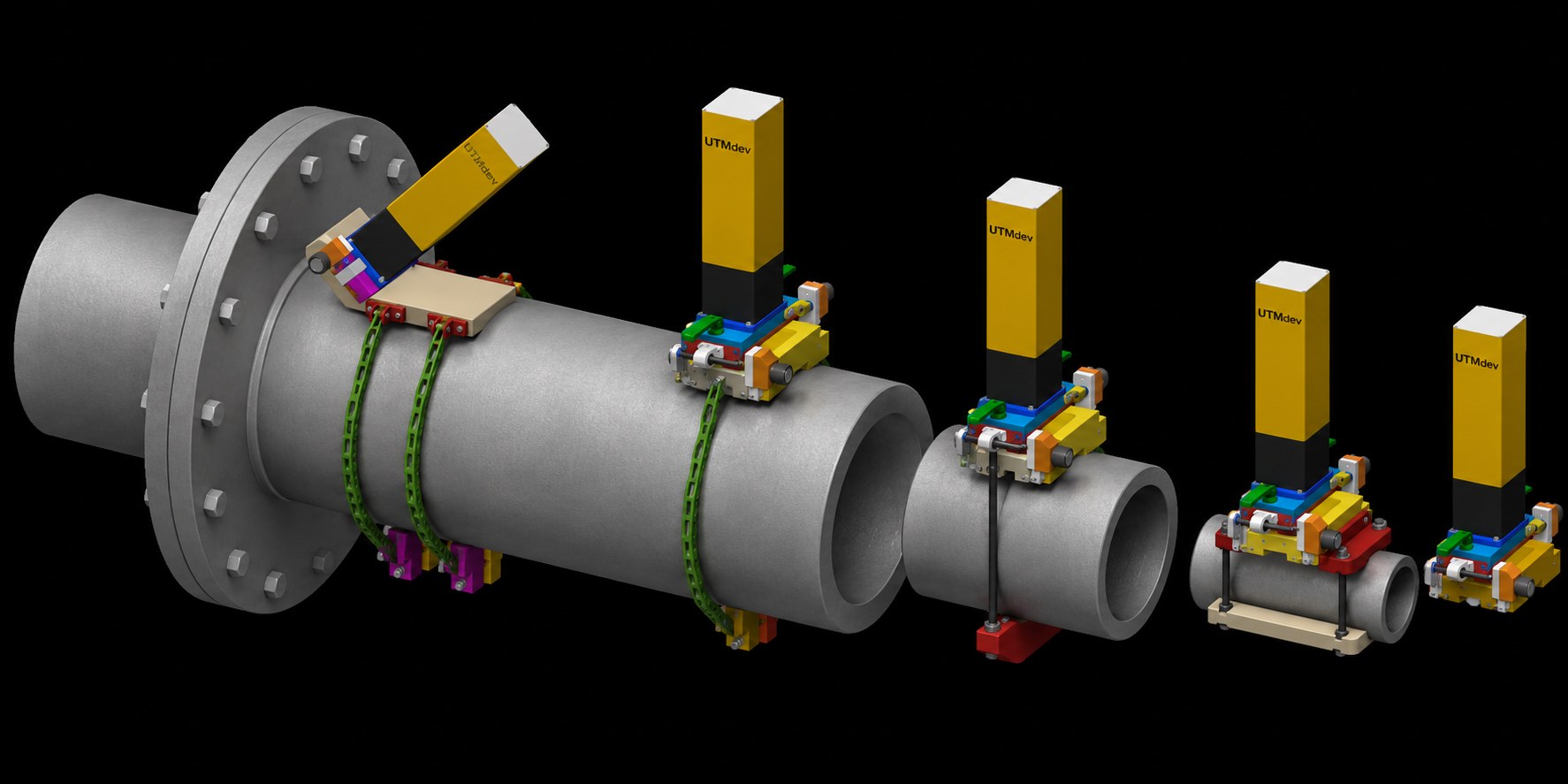
The clamping system adapts to the diameter and the shape of the component — from flanged joints through straight pipe runs to small sections and fittings. Measurement is possible on pipes, fillet and butt welds and flat surfaces.
 VISUALISATION
Dimensions and weights
- The tester itself
- 95 × 95 × 375 mm · 6.2 kg
- Tester in its case
- 540 × 430 × 210 mm · 9.7 kg
- Control unit in its case
- 480 × 390 × 190 mm · 10.3 kg
- Laboratory stand
- 155 × 150 × 175 mm · 7.6 kg
- Accessory case
- 540 × 430 × 410 mm · 17 kg
- XY positioning unit
- 275 × 250 × 135 mm · 4.7 kg
- Power supply
- 1 NPE 230 V AC 50 Hz, 10 A
- Alternatively
- 1 NPE 110 V AC 60 Hz, 20 A
- Surge protection
- EN 61643-11, SPD 1 and 2
Need the current mechanical properties and condition of critical components without cutting a test piece out of them?
Tell us which component and which material. We will come back with a technical solution and a schedule.
Materials
Product leaflet
A leaflet with more information about the product. This is only available upon request.
Request